

Some years ago a couple fellows I know were making some forward ‘V’ swept wing planes they called a Vortex. I built a few and flew them. They were made of built up balsa and used .25 FX glow engines. They were capable of some pretty impressive speed and maneuvers.
But today, I avoid glow fuel planes. I have started using electric motors and am still learning how to apply them. The Mini Electric Vortex is the latest plane I have been building. It is only similar to the original Vortex in appearance. Construction, size and shape is different along with electric power instead of glow fuel.
The parts and materials needed are:
- 2 – 1# density foam blocks 2-1/2″ x 7-5/8″ x 16″
- 11.5″ and 4.25″ lengths of 1-3/8″ square PVC tube
- 1/16″ x 3″ x 36″ balsa
- 1/8″ x 1″ x 28″ balsa
- GH MicroJet V3 Brushless Outrunner Motor
- YEP 30A (2~4S) SBEC Brushless Speed Controller
- 3 – Turnigy™ TGY-50090W Waterproof Analog Micro Servo w/Metal Gears
- FrSky TFR6-A 7ch 2.4Ghz Receiver Futaba FASST Compatible (Horizontal Connectors)
- APC 6x4E Electric Propeller
- Cutting Board for firewall
- Turnigy 850mAh 3S 60C Lipo Pack w/XT30
- XT30U-M Male Only (ESC Side) (5pcs)
- Linkage Stopper M3 x 2 x L11.2mm (10pcs/set)
- CA Hinge Sheet 180mmx140mmx0.3mm
- Medium Lock On Nylon Control Horn 10pcs
- Quick-Cure 5 Min Epoxy Glue 9. oz
- Carbon Fiber Rod 1.5mm x 300mm
- K&S Precision Metals Piano Wire 0.047″ x 12″
- 3M BLENDERM 1″x5 Yd Clear Surgical Plastic / RC Airplane Hinge Tape
The wings are 1# density foam cut with a hot wire to the wing shape. The foam cutting wire is mounted to a bow to keep the wire tight and connected to a power supply to maintain 3.1 amps in the wire. This keeps the heat at the correct temperature to cut the foam. See RC Foam Core Wings tutorial video on how to cut foam wing cores.
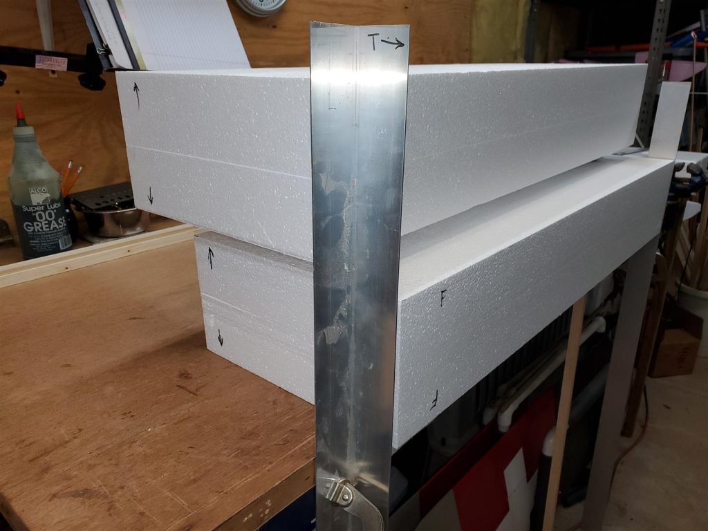
The Mini Vortex wings are cut the same way from a 2-1/2″ x 7-5/8″ x 16″ 1# density foam block. First the ends of the block are marked with a V to indicate up on the block. Also an arrow pointing to the front of the block is drawn on each end. Now a centerline is drawn on each end.

The aluminum templates are attached to the ends of the blocks on the centerline using finishing nails that have been sharpened.

Sand bags are used to hold the foam still while cutting.
Once the wire is up to temperature, carefully begin the cut. I start at the trailing edge. Be careful to go at a slow but steady speed. The templates must have very smooth edges. Keep the wire moving at the same speed at both ends. Apply firm but light pressure to ensure the wire stays in contact with the templates while cutting. The hot wire must exit at both templates at the same time to cut the correct shape on the leading edge of the wing.
Be careful to when marking the 15 degree angles to make a right and left wing. The wings are cut to 13-5/16″ long.


The cuts are made with the wings still in the shucks to keep the cuts square. Notice the masking tape to keep the shucks on tightly. The cuts can be made on a table saw or with the wire cutter. Be sure to mark the root of each wing. This will help avoid mistakes later.
Check out this posting to learn more about hotwire foam cutting.
Hotwire Foam Cutting
I use a couple of pieces of 1/16″ x 3″ aluminum angle attached to my work table to make these cuts. The aluminum angle is clamped to another piece of steel angle that is screwed to the underside of the table flush with the edge. I have smoothed the edge of the angle to ensure the wire slides smoothly while cutting.
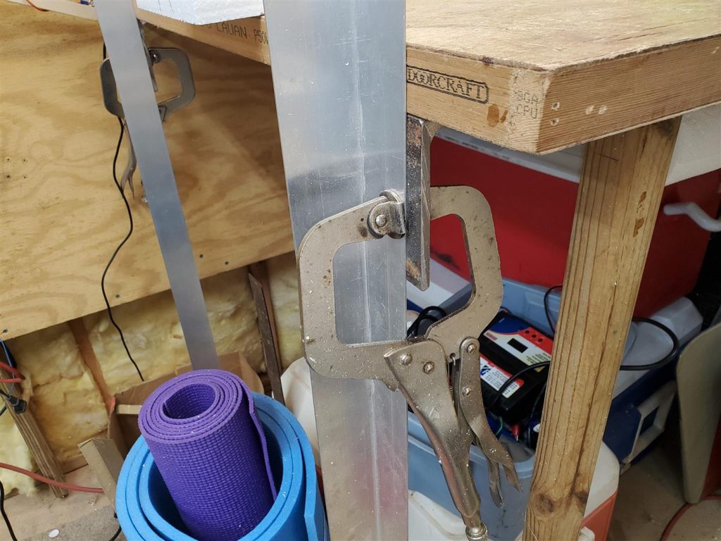

A straight edge is use to align the piece for cutting. Sand bags are used to hold the block of foam still while cutting. Be sure to catch the cutoff pieces to keep them from hanging on the wire as they come off especially if they are pieces to be used later.

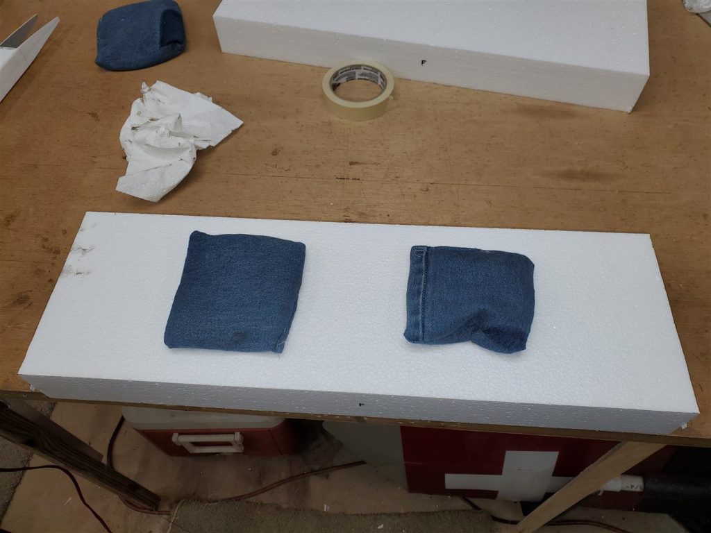
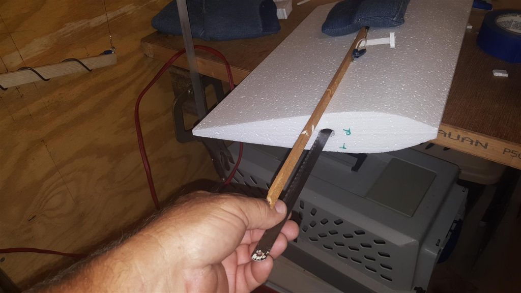
The two wings need holes for servo wires. Be sure the holes start at the root of the wing since the outboard end of the wings will not be covered. The holes can be made a number of ways. One is to heat the end of an old hacksaw blade and plunge it into the foam. This is risky, but can work if care is taken to stay square to the wing and not over heat the hacksaw blade. If the blade is too hot the hole will be too large and may exit the side of the wing.
I use a Foam Core Drill. You can see how it is made and used here.
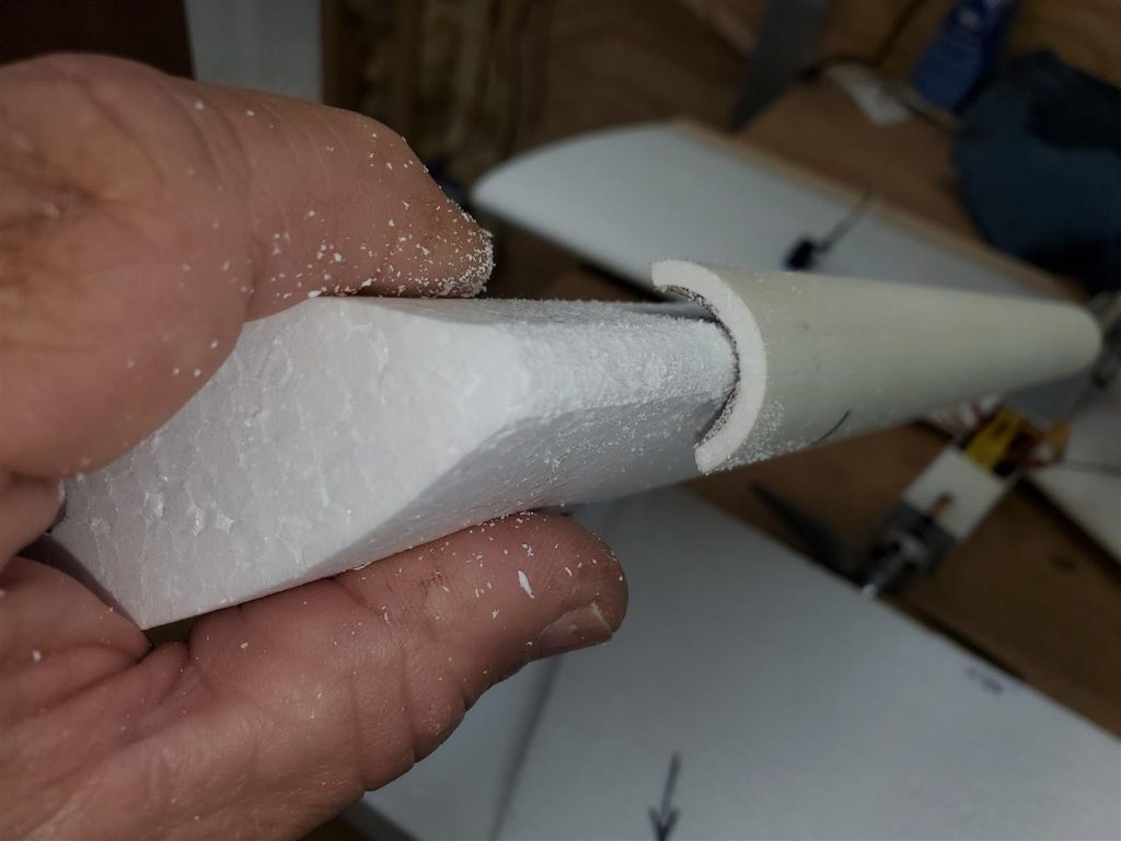
The leading edge is sanded over to a round shape with 80 grit sand paper attached to the inside section of PVC pipe that is cut in half lengthwise. Round it to your liking. I rounded mine to almost fit the sanding tool. Be careful not to let the sandpaper make a groove at the edges of the tool. Go slow and it will work out well.


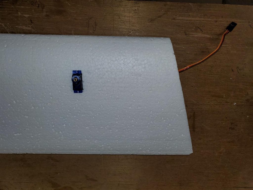
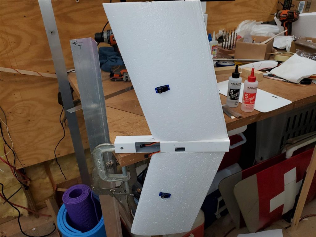
The servos are mounted 5.5″ out from the wing root measured over the servo lead hole. Be sure the servo wire end of the servo will be over the hole drilled into the wing for the servo wires. Mark the outline of the servo on the foam and cut out the foam for a snug fit. I use a Dremel Plunge Router attachment with a 1/8″ drywall cutting bit to remove the foam.

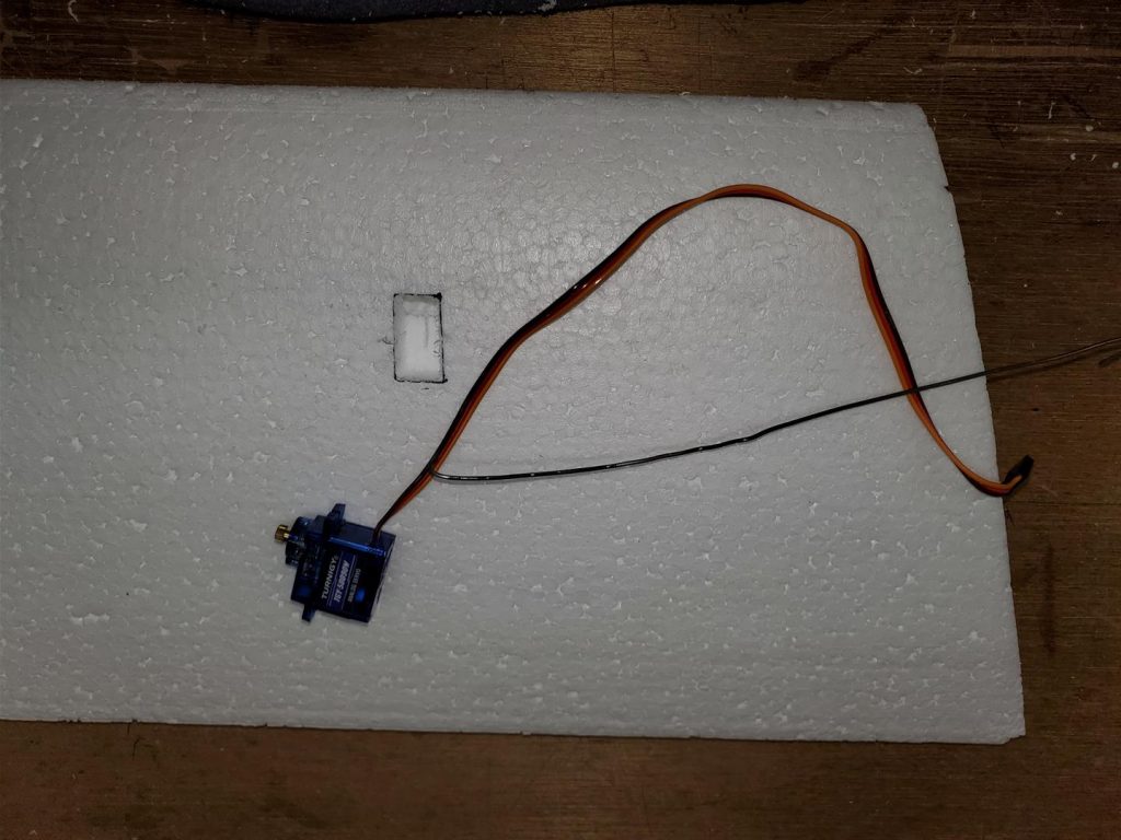
Fish the servo wire into the hole. Use hot glue sparingly to glue in the servos. Too much hot glue will melt a hole in the foam. (Ask me how I know!)
Next the fuselage is cut out. It is made of an 11.5″ length of 1-3/8″ square PVC tube. It is a picket from some PVC fencing I bought 20 years ago. We used to make combat planes with the PVC tube and Coroplast for flight surfaces. I think it is still available possibly at Lowes or Home Depot. I use a wood chisel to remove the pickets. Try to be careful not to damage the picket. The excess can be sanded off on a belt sander.
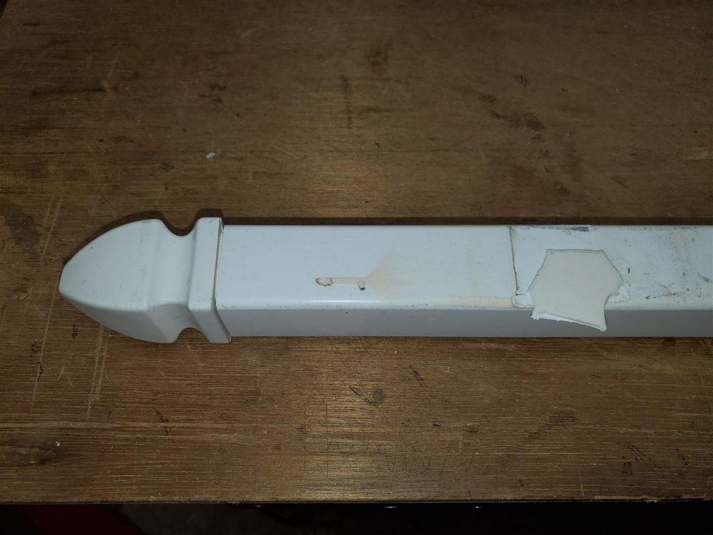

A hatch is cut in the top of the tube for battery and electronics access. The hatch can be cut with a thin saw and an Exacto knife. Be very careful not to cut yourself. The knife is used to score the cut many times until it cuts through.

Keep the piece removed for later attachment as the hatch cover.

Two holes are drilled to align with the servo wire holes in the wings.
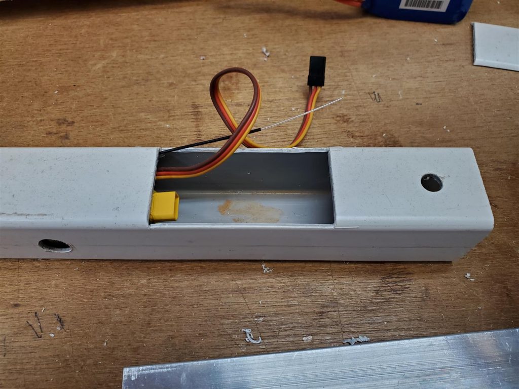
One hole is drilled in the top of the fuselage to run the motor leads in to the ESC motor connections.

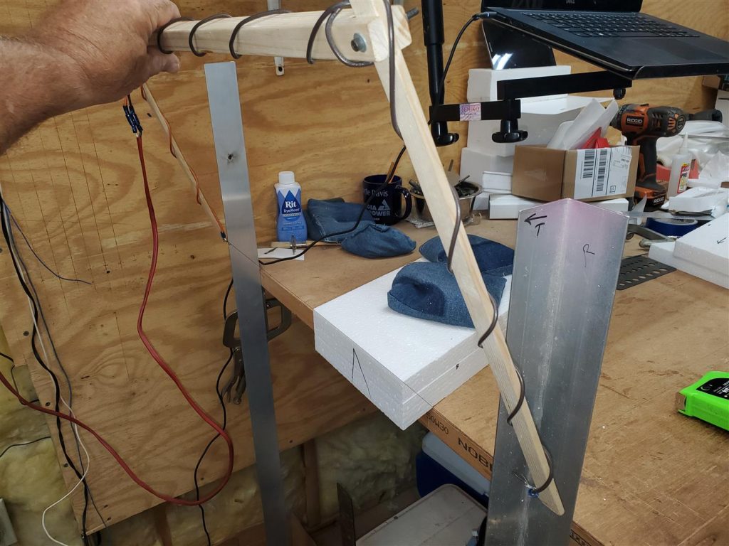
Test the c/g of the plane before attaching the wings. Mine balanced really close. Use a round pencil to lay the plane on with everything attached with tape. It may not be perfectly balanced, but it should be very close now, or later it will be difficult to adjust. The balance point is directly under the leading edge of the wing at the fuselage. Or it can be a little bit further forward to start. The ailerons and pushrods will add weight behind the c/g. I taped them on after the picture was taken and checked again. If the c/g is too far back it will only fly once!

A centerline is drawn on both sides of the fuselage to assist with aligning the wings. The fuselage is sanded with 80 grit sandpaper in the areas the wings will be attached. I also use a sharp object (a wood chisel) to make some deeper scratches to assure a good mechanical connection with the epoxy.
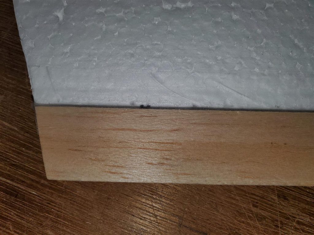
The wings are then attached to the fuselage with 5 minute epoxy. Be sure they stay aligned on the marked centerline. The first wing is attached with the fuselage laying on the table. The second wing is attached with the fuselage clamped to the table as shown.
The rudder servo is installed far enough back to allow the receiver and ESC room. A hole is cut to fit the servo and it is mounted to the fuselage with servo screws.

The firewall is made from some nylon or plastic cutting board material about 3/8″ thick. The motor is mounted directly to the firewall.

I re-threaded the four mounting holes to 6-32 thread so I could use some cap head screws to attach the motor. Make sure to keep the metal chips out of the motor.
I carefully, by hand, used a 1/4″ drill bit to counter sink the heads of the screws into the motor mount. This gives the battery a flat surface to rest on.

The hole in the center is to allow the shaft room to spin freely.
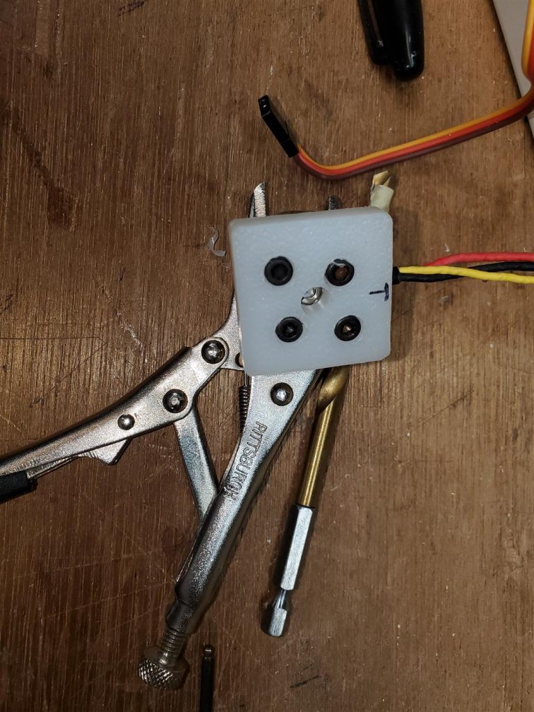
The motor windings could be shorted if the screws are too long. I cut the length of the screws to be sure they did not go into the motor too far.
The motor mount is inserted into the front of the fuselage and attached with three screws. One screw on top and two screws in the sides. The motor leads are pulled through into the fuselage. A piece of foam is put between the firewall and the battery.

The receiver and the ESC are taped together with the ESC motor leads rearward and the receiver connectors forward. I wrapped foam around them before installing them in the fuselage. I plan to change this arrangement later. I am concerned about the heat from the ESC affecting the receiver.

The fuselage in the picture above was abandoned. It was not long enough to allow balancing the plane and leaving the rear section of the PVC tube intact offers much more strength. I lengthened the fuselage to 11.5″ for balancing purposes.
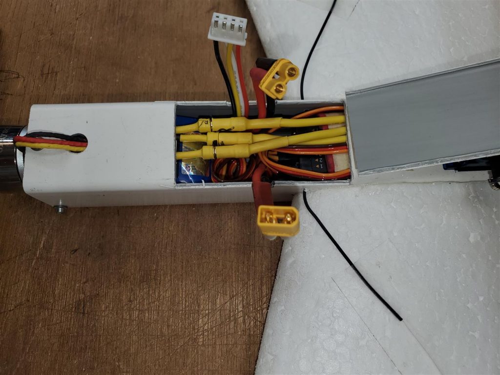
The ESC throttle lead and servos are connected to the receiver with the two aileron servos inserted into #1 and #6 positions. Most radios have an elevon wing mix to manage a flying wing. All the wires look to be a mess at first.

But once everything is in and connected, it looks much better.

If the ailerons do not operate properly for up and down and left and right throws, swap the servo leads in #1 and #6. Test again and everything should work. The receiver antennas are pulled through small holes to lay against the wing. Tape them down to the wing with Blenderm tape.
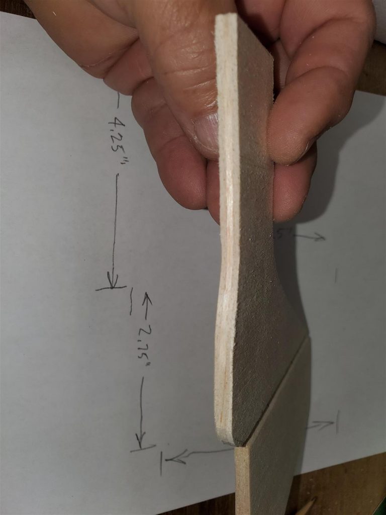
The vertical stabilizer and the rudder is made from some laminated 1/16″ thick balsa. I used CA to glue the pieces together. The grain is run up and down on the two sides and front to back on the inside. The shapes are cut from this laminated balsa.
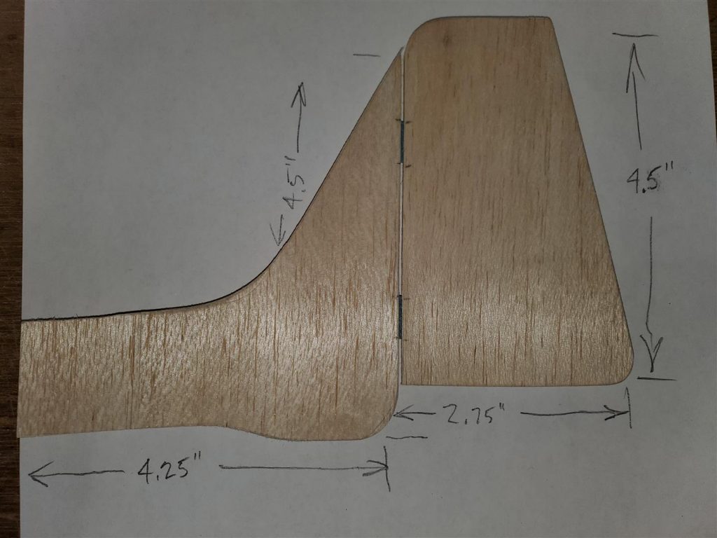
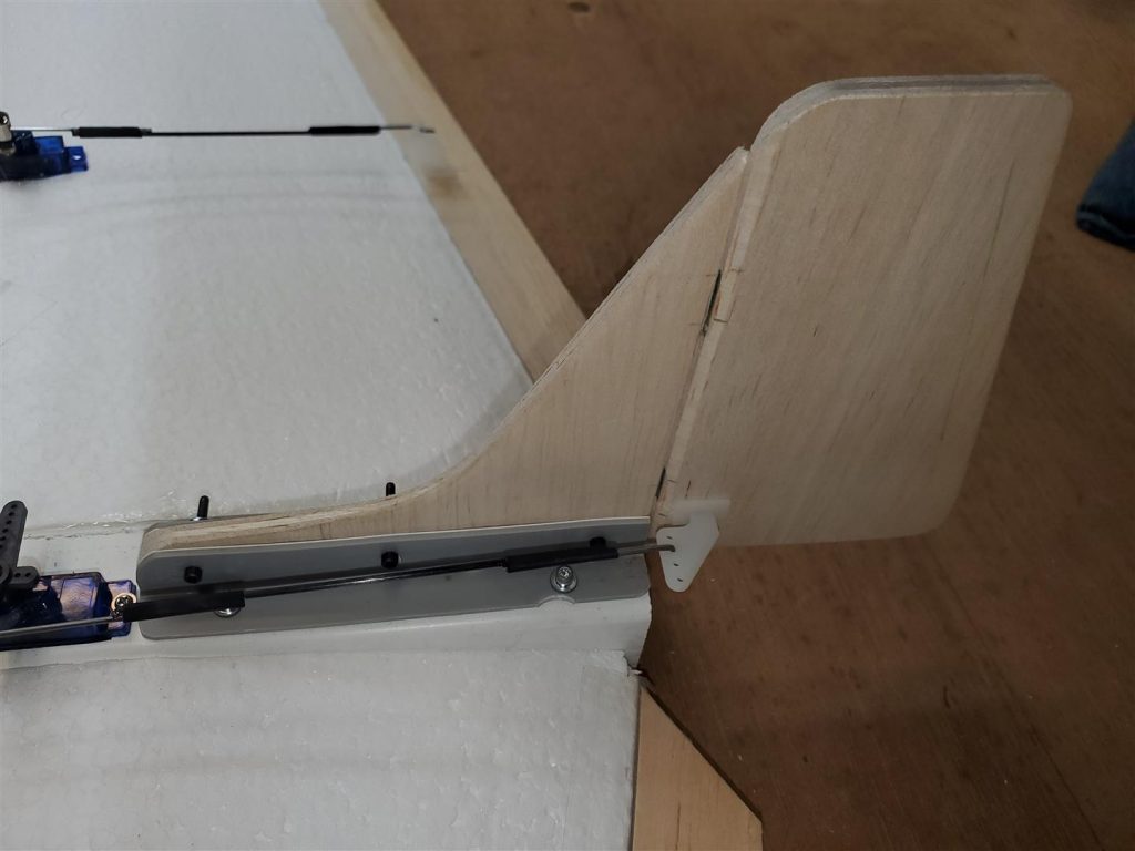
The hinges for the rudder are CA hinges.
The rudder can be attached to the fuselage several ways. I chose to use some pieces of the PVC tube as angles to attach the rudder. It is screwed onto the fuselage with some 2-56 screws with lock nuts through the angles and some servo screws to attach it all to the rear of the fuselage.

The ailerons are made from 1/8″ balsa. One edge is sanded to about a 45 degree edge.

They are attached to the wings with Blenderm tape. First tape the top edges leaving a very small gap.
Then fold the aileron onto the top of the wing and hold it down with some masking tape. Then attach some more Blenderm tape over the aileron, rear of the wing and under the wing.

The control horns are installed next along with centering the servos and installing the servo horns.

The pushrods are made from 1.5mm carbon fiber rod and music wire. The music wire is glued to the carbon fiber rod and a piece of heat shrink is applied. One end is a Z bend and the other straight.

The servo horns use a linkage stopper attachment listed above. Test and adjust all the flight surfaces. Check throw directions carefully.

Now make some slots for the battery leads and ESC lead out the sides of the hatch.

Tape the hatch cover on.

TEST EVERYTHING AGAIN! Be sure all the surfaces are correctly aligned and move in the correct direction. Be especially sure the motor spins in the correct direction before installing the 6×4 propeller.

Some color would make the plane easier to see. Maybe some water based paint will be added later. Also the hatch attachment will be improved later.
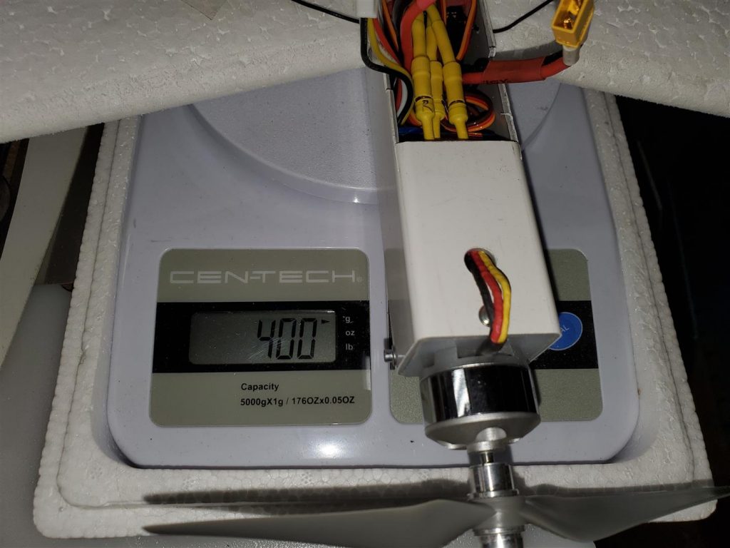
The plane should now be ready for its maiden flight. Mine is 400g ready to fly.
This is my Mini Electric Vortex maiden flight.
Let’s go fly!


